Line weights for floor plans: cut, below, overhead, and how few pens it takes
Line weights for floor plans follow one rule: what the plan cuts through is drawn heaviest, what you see below the cut is drawn lighter, and what sits above the cut is drawn broken. In ISO pens that usually means walls at 0.5 or 0.7 mm and almost everything else at 0.25 or 0.35 mm, with a lighter step for things far below. Set those widths once on the layers, not line by line, and the plan reads the same on every sheet.
What a plan actually is
A floor plan is a horizontal cut through the building about 1.2 m above the floor, looking down. That one idea decides every line weight on the sheet. Anything the cutting plane passes through, walls and columns, is in section. Anything below the plane that you can see, a worktop, a bath, the floor finish, is in elevation. Anything above the plane, a beam, a roof edge, a high-level cupboard, is out of sight and would be hidden if you were standing in the room.
ISO 7519 and ISO 128-23 put it plainly: what is cut is drawn wide, what is seen below narrow, and what is above the cut long-dashed double-dotted. Ching's Architectural Graphics gives the same hierarchy in the architect's usual terms: cut elements heaviest, elements seen below lighter, things far below lighter still, and things above the cut dashed. The two agree on the order. They differ only in whether the overhead line is a plain dash or a dash with two dots, so pick one for the office and keep to it.
How few widths it takes
ISO 128-2 says a drawing uses two line widths, wide and narrow, with the wide at least twice the narrow, both chosen from the standard series. The series is:
0.13, 0.18, 0.25, 0.35, 0.5, 0.7, 1, 1.4, 2 (mm)
The usual pair is 0.5 or 0.7 for outlines with 0.25 or 0.35 for the rest. Each step in the series is about √2 times the one before, which is why the pairs land at roughly two to one; the reasoning is laid out in line thickness in technical drawing.
Architectural plans often add one or two lighter steps below the narrow line, because a plan has more depth to show than a machine part: the furniture on the floor, then the paving and planting outside. That is still only three or four widths. If you find yourself reaching for a fifth or sixth, the hierarchy has stopped helping and the plan starts to look grey. The aim is that someone glancing at the sheet sees the walls first, the rooms second, and the detail last.
The hierarchy, element by element
| What it is | Where it sits | Line | Typical width (mm) |
|---|---|---|---|
| Walls and columns | Cut by the plan | Continuous wide | 0.5 or 0.7 |
| Doors, windows, stair treads, worktops | Seen below the cut | Continuous narrow | 0.25 or 0.35 |
| Furniture and fittings | Seen below the cut | Continuous narrow, a step lighter | 0.18 |
| Paving, planting, ground finishes | Far below the cut | Continuous narrow, lightest | 0.13 |
| Beams, roof edges, high units | Above the cut | Long-dashed double-dotted (ISO) or dashed (Ching) | Narrow |
| Hidden edges | Behind or under something | Dashed narrow (type 02.1) | Narrow |
| Structural grid | Setting out | Long-dashed dotted narrow (type 04.1) | Narrow |
| Section cutting plane | Marks where a section is taken | Long-dashed dotted wide (type 04.2) | Wide |
| Dimensions, extension lines, leaders, hatching | Annotation | Continuous narrow (type 01.1) | Narrow |
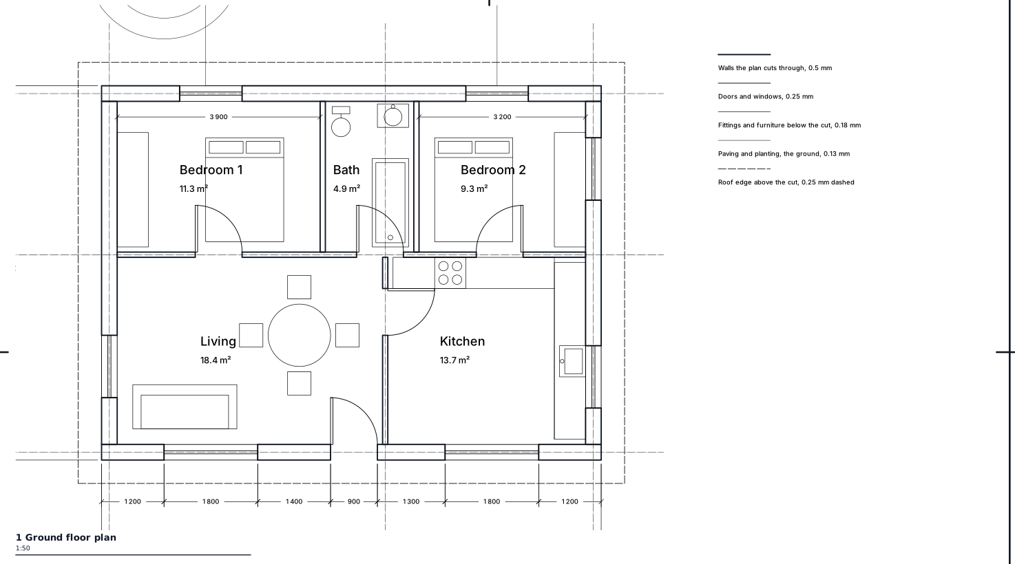
The drawing above is a cottage plan at 1:50 done exactly this way: walls at 0.5, doors and windows at 0.25, fittings and furniture at 0.18, paving and planting at 0.13, and the roof edge dashed at 0.25, with a key on the sheet.
Walls
The cut walls carry the drawing. Draw both faces wide, at their real thickness to scale, and dimension them to the face rather than the centre, in millimetres. If you hatch or fill the wall, the hatch is a narrow line; the wide line stays on the outline. The rules for section hatching are in hatching in engineering drawing.
Doors, windows and stairs
A door is the leaf drawn open at 90° with a quarter-circle for its swing. A window is lines across the wall thickness. A doorway with no door is just the gap. All of these are lighter than the wall they sit in, so the opening reads as a break in a heavy line. A stair shows its treads, a break line where it passes the cut (a continuous narrow freehand or zigzag line), and an arrow from the floor level marked UP. A ramp is drawn the same way with its gradient.
Furniture
Furniture is drawn as outlines at real size: a chair 450 to 500 wide, a desk 1400 × 700, a single bed 900 × 2000, a WC pan 380 × 700. It sits below the cut and is the least important thing in the room, so it goes on one of the lightest pens. Heavy furniture lines are the most common reason a plan looks cluttered.
Overhead
Anything above 1.2 m that matters to the plan, the edge of the roof or a floor above, a downstand beam, a rooflight, goes in a broken narrow line. It tells the reader something is there without competing with the walls.
Dashes that read properly
Broken lines are sized by the pen, not by eye. ISO 128-2 gives the dash and gap lengths as multiples of the line width d: a dash is 12d, a long dash 24d, a gap 3d, a dot at most 0.5d. So a dashed line reads four to one. Per millimetre of pen, the patterns are:
- Dashed: 12, 3
- Centre: 24, 3, 1, 3
- Phantom: 24, 3, 1, 3, 1, 3
- Dotted: 1, 3
A centre line or grid line extends a little past what it belongs to and starts and ends on a dash. If your overhead lines come out solid on the sheet, the line type scale is fighting the viewport scale; dashed lines printing solid covers the fix.
Where two lines fall on top of each other, ISO 128-24 gives the order: the visible outline wins over the hidden, the hidden over the centre line, the centre line over the extension line.
Line weights for site plans
A site plan uses the same idea with a different subject. The building, as the thing that matters most, gets the heaviest line. Boundaries and hard edges come next. Then the ground itself goes light:
- A tree is a circle at its mature canopy with the trunk at the centre.
- A hedge is a band.
- A slope is contour lines at even intervals, with every fifth heavier and labelled.
That heavier fifth contour is the site plan's own small hierarchy: it lets the reader count height without reading every label. Every plan, site or floor, carries a north point; orient north up, or the same way on every sheet of the set, and make sure the site plan agrees with the survey.
Set it on the layers, once
The quickest way to ruin a hierarchy is to set widths object by object. One wall gets drawn at the wrong pen, one chair gets copied in from an old job at 0.5, and the plan stops reading. Put each kind of thing on its own layer and give the layer its pen: walls, doors and windows, furniture, external works, overhead. Then you draw, and the weights look after themselves. A layer naming scheme helps; AIA layer standards shows how the names are built.
In isogram, each layer carries its pen from the ISO series, so walls, furniture and overhead lines are set once and print as they look. You draw at full size in Draft, lay the plan out on a sheet in Sheets, and the widths you see are the widths that come out of the PDF. If you open an existing DWG, its layers come across with it, so you can give an inherited job its pens in one pass rather than line by line.
A quick check before you plot
- Squint at the sheet. The walls should be the first thing you see.
- Count the widths. Three or four is plenty for a plan.
- Check the wide line is at least twice the narrow.
- Look for anything overhead drawn solid, and anything below drawn broken.
- Make sure furniture is lighter than doors and windows.
- Confirm the north point is there and agrees with the other sheets.
If you want to set up a plan this way and see the weights print true, you can try isogram when the public beta opens in December 2026, on the Mac and Windows first, with Linux following in an update.
Questions
What line weight should walls be on a floor plan?
Walls cut by the plan are drawn in the wide line, usually 0.5 or 0.7 mm from the ISO series. Everything else on the plan should be noticeably lighter, at least half that width.
How many line weights does an architectural plan need?
ISO 128-2 asks for two, wide and narrow, with the wide at least twice the narrow. Architectural plans often add one or two lighter steps for furniture and ground finishes, which makes three or four in all.
How do you show things above the cut on a floor plan?
Elements above the cutting plane, such as beams and roof edges, are drawn in a broken narrow line. ISO 7519 uses long-dashed double-dotted; Ching's architectural convention uses a plain dash.
Do line weights change between a floor plan and a site plan?
The principle is the same: the most important thing gets the heaviest line. On a site plan that is the building, with boundaries next and trees, hedges and contours lighter, and every fifth contour drawn heavier and labelled.
Should line weights be set by layer or by object?
By layer. Giving each layer its pen means every wall, door or chair placed on it takes the right width automatically, and a copied-in object cannot quietly break the hierarchy.
14 November 2026
The public beta opens in December.
Join the list and we'll email you the download link when it opens. It's free to test.
Join the listMore guides
- Line thickness in technical drawing: the ISO widths and why they go up by √2The ISO 128 line widths from 0.13 to 2 mm, why each is √2 times the last, the wide and narrow pair, and which line type takes which width.
- NCS sheet numbering: reading A-101, the sheet type digits and the set orderHow an NCS sheet number like A-101 is read: discipline, sheet type digit and sequence, what each digit 0 to 9 means, and the order the set is bound in.
- Hatching in engineering drawing: every rule for a section, and whyHatching in engineering drawing per ISO 128-50: the 45° angle, 2.5 to 4 mm spacing, adjacent parts, thin sections, large areas and text, each with why.
- Dashed line not showing in AutoCAD layout: the fix, and why it happensDashed line not showing in an AutoCAD layout? Set LTSCALE, PSLTSCALE and MSLTSCALE, run REGENALL, and see why dashes vanish at a viewport scale.
- What should a title block include: the required fields, the extras, and where it goesThe fields every title block must have under ISO 7200, the ones engineering and architecture add, and where the block sits on the sheet.
- Standard text height for architectural drawings, sheet by sheetISO 3098 text heights for architectural drawings: the series from 1.8 to 20 mm, sizes for notes, dimensions and titles, and the smallest that prints.