Dashed line not showing in AutoCAD layout: the fix, and why it happens
If a dashed line is not showing in your AutoCAD layout, set LTSCALE to 1, PSLTSCALE to 1 and MSLTSCALE to 1, then type REGENALL. That makes AutoCAD scale every linetype by the viewport's scale, so the dashes come out the same length on the sheet in every viewport. If a line still draws solid after that, it's shorter than one dash, or the object carries its own linetype scale.
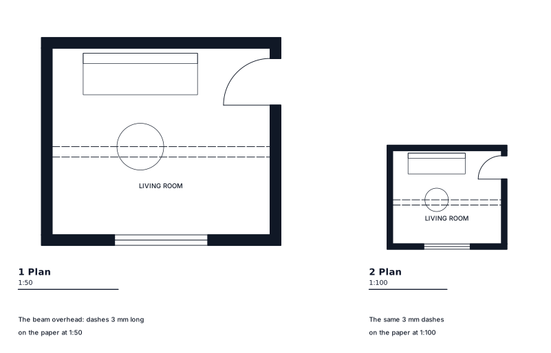
The fix, step by step
Work through these in order. Most of the time the first four steps are all you need.
- Set the global scale. Type
LTSCALEand enter 1. This is the global linetype scale, and it multiplies every dash in the drawing. - Set the paper space scaling. Type
PSLTSCALEand enter 1. With this on, linetypes in paper space viewports are scaled by each viewport's scale, so a dash looks alike in a 1:50 viewport and a 1:100 viewport on the same sheet. - Set the model space scaling. Type
MSLTSCALEand enter 1. With this on, linetypes in model space are scaled by the annotation scale, so the model tab looks like the sheet will. - Regenerate. Type REGENALL. The settings don't show until every viewport is redrawn. This is the step most people miss: they change the variable, nothing moves, and they change it back.
- Check the object itself. Select the line and look at its linetype scale in Properties. Each object keeps the scale it was drawn with, which comes from
CELTSCALE, the scale for new objects. If someone setCELTSCALEto an odd value before drawing, those lines carry it. Set the object's scale back to 1, and setCELTSCALEto 1 so new lines don't repeat the problem. - Check the line's length. A dash longer than the line it sits on draws the line solid. A short hidden edge on a small detail may simply be too short for one dash and one gap.
- Check the linetype file. If you draw in millimetres, the linetypes should come from
acadiso.lin, which defines the ISO linetypes in millimetres. A linetype defined for other units will be the wrong size before any scale is applied.
The usual working settings are LTSCALE 1, PSLTSCALE 1 and MSLTSCALE 1, followed by REGENALL. If you inherit drawings from other offices, check these three every time you open a new file, because they're saved in the drawing.
Why the dashes disappear
A linetype is a pattern of dashes and gaps, and in AutoCAD the lengths are numbers in the drawing's units. You draw the building at full size in model space, so a dash defined as a few millimetres is a few millimetres long in the model, next to walls that are thousands of millimetres long.
Now put that model behind a viewport at 1:100. Everything in the viewport is shrunk a hundredfold, including the dash. A dash that was a few millimetres in the model becomes a tiny fraction of a millimetre on the paper. The gaps shrink too, and they get so small that the printer or the screen fills them in. The line looks continuous. Nothing is broken; the pattern is just too fine to see.
At 1:50 the shrink is half as bad, so on a sheet with two viewports you can get dashes that nearly work in one window and a solid line in the other. That's the "linetype scale different in model and layout" symptom, and it's the same cause.
PSLTSCALE set to 1 undoes the shrink. AutoCAD multiplies the dash by the viewport's scale before drawing it, so after the viewport shrinks it, the dash lands on the paper at the length the linetype file intended. MSLTSCALE does the same job in model space, using the annotation scale.
Why the forum advice conflicts
Search this problem and you'll find threads telling you to set PSLTSCALE to 0, threads telling you to set it to 1, and threads telling you to set LTSCALE to your drawing scale. They're describing two different ways of working.
- The old way: leave
PSLTSCALEat 0 and setLTSCALEto the scale factor of the drawing. The dashes are made big in the model so they survive the shrink. This works when every viewport is at one scale. Add a detail at another scale and its dashes come out the wrong size, because one global number can't suit two scales. - The viewport way: leave
LTSCALEat 1, setPSLTSCALEto 1, and let each viewport scale its own dashes. This works with any mix of scales on a sheet.
Mixing the two is what goes wrong. If LTSCALE is set to a scale factor and PSLTSCALE is 1, the dashes are scaled twice and come out huge, so a short line shows as one long dash, which also reads as solid. That's why someone on a forum says "turn PSLTSCALE off" and it works for them: they had the old setup. Pick the viewport way, set all three to 1, and run REGENALL.
What the dash should actually measure on paper
Once the scale is right, it helps to know what you're aiming for. ISO 128-2 sets dash and gap lengths as multiples of the line width, d: a dash is 12d, a long dash 24d, a gap 3d, and a dot at most 0.5d. So a dashed line reads four to one, dash to gap, whatever pen it's drawn with.
| Line | ISO type | Pattern, per mm of pen | Used for |
|---|---|---|---|
| Dashed narrow | 02.1 | 12, 3 | Hidden outlines and edges |
| Long-dashed dotted narrow | 04.1 | 24, 3, 1, 3 | Centre lines, lines of symmetry |
| Long-dashed dotted wide | 04.2 | 24, 3, 1, 3 | Cutting planes |
| Long-dashed double-dotted narrow | 05.1 | 24, 3, 1, 3, 1, 3 | Adjacent parts, alternative positions |
| Dotted | 1, 3 |
Hidden lines are narrow. The usual pair is 0.5 or 0.7 mm for outlines with 0.25 or 0.35 mm for the rest, picked from the standard series of 0.13, 0.18, 0.25, 0.35, 0.5, 0.7, 1, 1.4 and 2 mm. The wide line should be at least twice the narrow. A centre line starts and ends on a dash and runs a little past the outline it belongs to, and where lines fall on top of each other the visible outline wins over the hidden, the hidden over the centre line, and the centre line over the extension line. That last rule matters for "hidden line not showing": if a hidden edge sits exactly under a visible one, the visible one is meant to win.
A dash defined on the paper never has this problem
Every step above exists to correct one thing: the dash is measured in the model, and the sheet is where it has to look right. If the dash is measured on the paper in the first place, there's nothing to correct.
That's how isogram handles it. Dash lengths are set in paper millimetres from the ISO table, scaled to the pen, so a dash is the same length on the sheet at every viewport scale and there's no linetype scale to set. You draw at full size in Draft, lay the views out on Sheets with viewports, and the dashes follow ISO 128 on their own. In the drawing above, one room sits at 1:50 and at 1:100 on an A3 sheet, and the beam's dashes are 3 mm long with 0.75 mm gaps on the paper in both windows.
It's the same idea isogram uses for lettering: text height is set as the height on the printed sheet, and the app works out its size in the drawing from the scale. If you've been doing that sum by hand, text height for scale covers it. And if your viewport scales go wrong when a sheet is printed smaller than it was drawn, see why 1:50 at A1 becomes 1:100 on A3.
Before a set goes out, isogram also reads every sheet for the things a senior drafter would catch, such as lettering too small to print or an empty title block field, so problems show up before the client sees them.
If you're switching from AutoCAD
You don't have to start your drawings again. isogram opens DWG files from R13 to the 2018 format, and DXF, bringing in lines, arcs, polylines, text, hatches, blocks and layers; opening DWG files explains what comes across. The command line takes the AutoCAD aliases, and F3, F8 and F10 do what your hands expect; the full list is in AutoCAD commands in isogram. It runs on a Mac with Apple silicon, on Windows and on 64-bit Linux.
The public beta opens in December 2026, on the Mac and Windows first, with Linux following in an update, and it's free to test. If you'd rather never type REGENALL to find a dash again, join the list and the download link comes by email.
Questions
What LTSCALE should I use for a 1:100 drawing?
With PSLTSCALE set to 1, leave LTSCALE at 1. The viewport's own scale takes care of the dash length, so you don't set LTSCALE to the drawing scale.
Which linetype file should I load for a metric drawing?
Load linetypes from acadiso.lin, which defines the ISO linetypes in millimetres. That way the dash lengths are in the same units as the drawing before any scale is applied.
How thick should a hidden line be?
Hidden lines are dashed narrow lines, ISO type 02.1. With outlines at 0.5 or 0.7 mm, the narrow line is usually 0.25 or 0.35 mm.
Do the linetype scale settings carry over to other drawings?
LTSCALE, PSLTSCALE and MSLTSCALE are saved in each drawing, so a file from another office can arrive with different values. Check all three when you open it and run REGENALL after changing them.
5 November 2026
The public beta opens in December.
Join the list and we'll email you the download link when it opens. It's free to test.
Join the listMore guides
- Text height for scale 1:100: the sum, the chart, and how to stop doing itText height at 1:100 is the paper height times 100: 2.5 mm prints from 250 mm. A chart for every usual scale, and how to skip the sum entirely.
- AIA layer standards: how a name is built, the layers you need, and N, E, DHow an AIA (NCS) layer name is built from discipline, major group, minor group and status, the layers an architectural set needs, and -N, -E, -D.
- Drawing revision letters not used: which ones, why, and what comes after ZWhich revision letters drawings skip and why, the full sequence from A to AA and beyond, and how to write a revision row above the title block.
- Scale 1:50 at A1 printed on A3: why it becomes 1:100An A1 drawing at 1:50 printed on A3 measures 1:100. The A-size arithmetic, a quick converter table, and why to write 1:50 @ A1 with a scale bar.
- ISO 5457 A3 border size: the frame, margins, marks and grid, size by sizeThe ISO 5457 A3 border: 20 mm filing margin, 10 mm on the other edges, centring marks, a 50 mm grid and where the title block sits, for A0 to A4.
- ISO 7200 title block, field by field, on any sheet sizeThe ISO 7200 title block field by field: the nine mandatory fields, the optional ones, the 180 mm width limit and where it sits on A0 to A4 sheets.
AutoCAD is a registered trademark of Autodesk, Inc. isogram is not affiliated with or endorsed by Autodesk.