Hatching in engineering drawing: every rule for a section, and why
Hatching in engineering drawing follows ISO 128-50: a cut face is filled with continuous narrow lines at 45° to the part's main outline or axis, usually spaced 2.5 to 4 mm apart on paper. Adjacent parts differ by angle or spacing, thin sections go solid black, and the hatching stops for any text inside it. Here is every rule in one place, with the reason behind each.
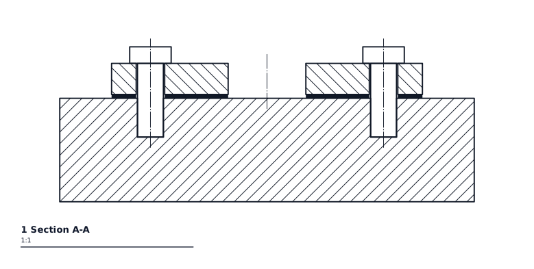
The rules below come from ISO 128-50:2001 for the hatching itself and ISO 128-3:2020 for the cutting plane and the section view. A few are conventions rather than clauses, and they're marked as such. In the drawing above you can see most of them at once: two parts hatched in different directions, a gasket filled solid, and bolts left clear.
The angle: 45° to the outline or axis
A cut face is hatched with continuous narrow lines at 45° to the main outline or the axis of the part (ISO 128-50:2001 §5.1). Note what the 45° is measured from: the part, not the sheet. On most parts the main outline is square to the sheet, so the two come to the same thing. On a part drawn at an angle, the hatching turns with it.
Why: outlines are mostly horizontal and vertical. A line at 45° can't be mistaken for an edge, so the eye reads "cut material" at a glance and the true outline stays clear. Measuring from the part's own axis keeps that true even when the part isn't square to the sheet.
The line: narrow and continuous
Hatching is ruled at the narrow line width, in continuous lines. Not dashed, not wide.
Why: the visible outline of the section is a wide line. If the hatching matched it, the boundary of the part would disappear into the fill. Keeping hatching narrow puts it in the background, where it belongs: it tells you the material is cut, while the outline tells you the shape.
The spacing: chosen to the area, never merging
Spacing is chosen to suit the size of the area, and it must never be so close that the lines merge (ISO 128-50:2001 §5.2). By convention the pitch on paper is usually 2.5 to 4 mm. Smaller areas sit at the tight end, larger ones at the open end.
The important words are on paper. A hatch is chosen against the printed sheet. Zooming on screen never changes it, and the drawing's scale shouldn't either: a 3 mm pitch should print as 3 mm whether the view is at 1:1 or 1:10. In CAD that means the pattern scale has to account for the view scale. Get it wrong one way and the lines print so close they fill in grey; get it wrong the other way and a small part shows one stray line or none.
Watch reduced prints too. A sheet drawn for A1 and printed on A3 shrinks everything, hatch pitch included, and a pitch that was fine at full size can close up. The same thing happens to the scale itself, covered in why 1:50 at A1 becomes 1:100 on A3.
Why: hatching that merges reads as a grey blot and hides any detail inside it. Hatching that's too open looks like stray construction lines. Fitting the spacing to the area keeps it readable at the size it will actually be seen.
The same part, the same hatching, in every section
One part is hatched the same way, at the same angle and the same spacing, in every section on the drawing (ISO 128-50:2001 §5.3). If the housing is at 45° with a 3 mm pitch in section A-A, it's at 45° with a 3 mm pitch in section B-B too.
Why: the reader uses the hatching to identify the part. When they flip from one section to the next, a matching pattern tells them it's the same piece of metal cut in a different place. Change it and they'll assume it's a different part.
Adjacent parts: differ by angle or spacing
Where two parts touch in a section, their hatching differs by angle or by spacing (ISO 128-50:2001 §5.3). The usual move is to turn the second part's hatching the other way. In the drawing above, the base is hatched at 45° and the plate at 135°, so the two read apart even though they share an edge. A third part touching both can take a different spacing.
Why: where two cut faces meet, the line between them is easy to lose. A change of direction or pitch makes the joint obvious without adding anything to the drawing, and it tells the reader immediately that these are two parts, not one.
Thin sections: solid black
A section too thin to hatch, such as a gasket, a sheet or a thin plate, is shown solid black. Where two thin sections sit side by side, leave at least 0.7 mm clear between them (ISO 128-50:2001 §5.5). The gasket in the drawing above is filled solid.
Why: you can't fit hatching at a readable pitch into a strip a millimetre or two wide; you'd get one line or a smudge. Solid fill reads clearly. The 0.7 mm gap exists because two black strips touching look like one thick part, and the gap is what tells the reader there are two.
Large areas: hatch along the outline
A large cut area may be hatched along its outline only, in a band just inside the boundary, with the middle left clear (ISO 128-50:2001 §5.4).
Why: a big field of hatching adds nothing beyond what a border of it says, and it makes the view heavy and harder to read. Hatching the edge still marks the area as cut material, and it leaves room for anything else that needs to sit inside the view.
Text inside a hatched area: break the hatching
If a dimension figure or a note has to go inside a hatched area, the hatching is interrupted around it. It's never drawn through the text (ISO 128-50:2001 §5.6).
Why: a figure with lines running through it can be misread, and a misread dimension becomes a scrapped part. Clearing a small gap around the text keeps every character legible. In CAD, most hatch tools can treat a text object as an island and leave space around it, which is far better than trimming lines by hand.
What is not hatched
Solid parts such as shafts, bolts, pins, ribs and spokes are not hatched when the cutting plane runs along their length (ISO 128-3:2020 §10.5). They're drawn in outline as if uncut. The two bolts in the drawing above, cut along their length, are left unhatched.
Why: cutting a solid bolt lengthwise shows nothing a plain view doesn't, and hatching it would make it look like a bigger body than it is. A rib hatched in a lengthwise cut looks like a solid wall, which misleads the reader about the part's real shape. Leaving these clear keeps the section honest. When the same parts are cut across, they are hatched as normal.
The cutting plane and the section title
Hatching only makes sense if the reader knows where the cut was taken. ISO 128-3:2020 §10 covers that:
- The cutting plane is a long-dashed dotted line (ISO 128-2 type 04.2). It's wide at its ends and where it changes direction, and narrow in between.
- Arrows at the ends point in the direction of viewing.
- A capital letter stands at each end, and the section view is titled with the pair, such as A-A, above the view (§10.2).
- The letters are capitals, one size larger than the dimension figures.
- The section is drawn where projection would place it, or somewhere else on the sheet as long as it's titled (§10.4).
If the long-dashed dotted line prints solid, the line type scale is usually the culprit; see dashed lines that print solid for the fix.
Why: the wide ends and corners show exactly where the plane starts, stops and turns, while the narrow middle keeps it from cluttering the view it crosses. The letters tie the cut to its view, so a reader can find section A-A from the mark, or the mark from the section.
On building drawings
Architectural sets follow a different convention, from ISO 7519:1991 (BS EN ISO 7519). The section mark is a circle at each end of the line, carrying the section letter over the number of the sheet the section is drawn on. The arrow is a filled triangle on the circle. The reason is the size of the set: on a building, the section is often several sheets away from the plan, and the sheet number tells you where to look.
The rules at a glance
| Rule | What to do | Source |
|---|---|---|
| Angle | 45° to the main outline or axis | ISO 128-50:2001 §5.1 |
| Line | Continuous, narrow width | ISO 128-50:2001 |
| Spacing | To suit the area, never merging; usually 2.5 to 4 mm on paper | ISO 128-50:2001 §5.2; convention |
| Same part | Same angle and spacing in every section | ISO 128-50:2001 §5.3 |
| Adjacent parts | Differ by angle or by spacing | ISO 128-50:2001 §5.3 |
| Large area | May be hatched along its outline only | ISO 128-50:2001 §5.4 |
| Thin section | Solid black, at least 0.7 mm between adjacent ones | ISO 128-50:2001 §5.5 |
| Text inside | Interrupt the hatching, never draw through | ISO 128-50:2001 §5.6 |
| Shafts, bolts, ribs, spokes cut lengthwise | Not hatched | ISO 128-3:2020 §10.5 |
| Cutting plane | Long-dashed dotted, wide at ends and turns | ISO 128-3:2020 §10 |
Hatching sections in isogram
isogram is 2D CAD for architects and engineers, and its hatching follows ISO 128-50, with dimensions to ISO 129-1, lines to ISO 128 and lettering to ISO 3098. It has ruled and grown hatch patterns. You draw at full size in Draft and lay out the sheets with viewports in Sheets, the same split as model space and paper space. Text height is set as the height on the printed sheet in millimetres, and the app works out its size on the drawing from the scale, so the A-A title and the dimension figures inside a section come out the size you meant (the sum behind that is in text height for scale).
Before a set goes out, isogram reads every sheet for what a senior drafter would catch, such as lettering too small to print, an empty title block field or two sheets with one number. Existing work comes in too: hatches come across from DWG files from R13 to the 2018 format, along with lines, blocks and layers.
The public beta opens in December 2026 on the Mac and Windows, with Linux following in an update, and it's free to test. If you want to try it on your own sections, join the list and the download link will come by email.
Questions
What angle should hatching lines be in an engineering drawing?
45° to the main outline or axis of the part, per ISO 128-50:2001. For an adjacent part, turn the hatching the other way or change its spacing so the two read apart.
What is the standard spacing for section hatching?
ISO 128-50 says to choose the spacing to suit the size of the area and never so close the lines merge. By convention that's usually 2.5 to 4 mm on the printed sheet.
Which ISO standard covers hatching?
ISO 128-50:2001 covers how cut faces are hatched. ISO 128-3:2020 covers the cutting plane, the section labels and which parts are left unhatched.
Do you hatch bolts and shafts in a section view?
Not when the cutting plane runs along their length. Shafts, bolts, ribs and spokes cut lengthwise are drawn unhatched under ISO 128-3:2020.
How do you show a gasket in section?
A thin section such as a gasket or sheet is filled solid black. Where two thin sections sit next to each other, leave at least 0.7 mm clear between them.
9 November 2026
The public beta opens in December.
Join the list and we'll email you the download link when it opens. It's free to test.
Join the listMore guides
- Drawing revision letters not used: which ones, why, and what comes after ZWhich revision letters drawings skip and why, the full sequence from A to AA and beyond, and how to write a revision row above the title block.
- Tolerance block on drawings: both styles, with a worked example of eachHow a tolerance block on drawings states the general tolerance: an ISO 2768 class or a decimal-places block, with worked examples and when each is used.
- ISO 5457 A3 border size: the frame, margins, marks and grid, size by sizeThe ISO 5457 A3 border: 20 mm filing margin, 10 mm on the other edges, centring marks, a 50 mm grid and where the title block sits, for A0 to A4.
- AIA layer standards: how a name is built, the layers you need, and N, E, DHow an AIA (NCS) layer name is built from discipline, major group, minor group and status, the layers an architectural set needs, and -N, -E, -D.
- Dashed line not showing in AutoCAD layout: the fix, and why it happensDashed line not showing in an AutoCAD layout? Set LTSCALE, PSLTSCALE and MSLTSCALE, run REGENALL, and see why dashes vanish at a viewport scale.
- Scale 1:50 at A1 printed on A3: why it becomes 1:100An A1 drawing at 1:50 printed on A3 measures 1:100. The A-size arithmetic, a quick converter table, and why to write 1:50 @ A1 with a scale bar.