Line thickness in technical drawing: the ISO widths and why they go up by √2
Line thickness in technical drawing comes from one series of widths: 0.13, 0.18, 0.25, 0.35, 0.5, 0.7, 1, 1.4 and 2 mm. A drawing uses two of them, a wide and a narrow, with the wide at least twice the narrow. The usual pair is 0.5 or 0.7 mm for visible outlines and 0.25 or 0.35 mm for everything else.
That's the short answer, and it's what ISO 128-2 sets out. The rest of this page covers why the series climbs the way it does, how to pick the pair, which line type takes which width, and how the dashes are sized from the pen.
The line width series
ISO 128-2 doesn't let you pick any width you like. Every line on the sheet comes from this list:
| Width (mm) | Step up from the last | Typical use |
|---|---|---|
| 0.13 | (start) | Narrow lines on small, fine drawings |
| 0.18 | × √2 | Narrow lines in the 0.35 group |
| 0.25 | × √2 | Narrow lines in the 0.5 group |
| 0.35 | × √2 | Narrow lines in the 0.7 group, or wide lines on a light drawing |
| 0.5 | × √2 | Wide lines, the common choice for outlines |
| 0.7 | × √2 | Wide lines on larger sheets |
| 1 | × √2 | Wide lines on large or heavy drawings |
| 1.4 | × √2 | Wide lines, rarely needed |
| 2 | × √2 | The top of the series |
Check any pair of neighbours and you'll find the ratio is the same: 0.25 × 1.414 is 0.354, so 0.35. 0.5 × 1.414 is 0.707, so 0.7. 1 × 1.414 is 1.414, so 1.4. The widths are rounded, but the rule behind them is exact: each one is √2 times the one before it.
Why the series goes up by √2
This is the part most line weight charts leave out, and it's the reason the series looks odd at first.
The A series of paper is built on the same ratio. Each sheet's sides stand in the ratio 1 to √2, and folding one in half gives the next size down. So when you print a drawing one paper size smaller, say A1 on to A2, every length on the sheet shrinks by a factor of √2. That includes the thickness of every line.
Now follow a line through that reduction:
- A 0.7 mm outline divided by 1.414 comes out at 0.495 mm. That's 0.5, the next width down.
- A 0.35 mm narrow line comes out at 0.247 mm. That's 0.25.
- So a drawing in the 0.7 and 0.35 pair, printed one size down, becomes a drawing in the 0.5 and 0.25 pair.
The reduced print is still a correct drawing. Every line lands on a standard width, the wide is still twice the narrow, and the drawing reads the same, just smaller. Enlarging works the same way in the other direction. If the widths went up in any other ratio, a reduced print would end up with widths that belong to no group at all.
Two steps of √2 make a factor of 2. That's why the narrow line in each group sits exactly two places below the wide one: 0.5 with 0.25, 0.7 with 0.35, 1 with 0.5. It's also why printing two sizes down halves every line. A1 on A3 turns 1:50 into 1:100, and a 0.5 and 0.25 drawing into a 0.25 and 0.13 one. The narrow lines are now at the bottom of the series, which is worth knowing before you send a reduced set to site. The scale side of that is covered in why 1:50 at A1 printed on A3 becomes 1:100.
Choosing the wide and narrow pair
ISO 128-2 asks for two widths per drawing, both from the series, with the wide at least twice the narrow. In practice you pick a wide width and take the narrow two steps below it.
- 0.5 and 0.25: the everyday pair for part drawings and most general arrangements.
- 0.7 and 0.35: for larger sheets, or drawings that will be reduced for issue.
- 0.35 and 0.18: for small, detailed views where heavier lines would clog.
Pick one pair for the whole set and stick with it. The point of the two widths is that the reader sees the object first and the information about it second. Mixing groups between sheets breaks that.
Which line takes which width
Each line type in ISO 128-2 has a number. The part after the point tells you the width: .1 is narrow, .2 is wide.
| Type | Line | Width | Used for |
|---|---|---|---|
| 01.2 | Continuous | Wide | Visible outlines and edges |
| 01.1 | Continuous | Narrow | Dimension lines, extension lines, leaders, hatching, short centre lines |
| 01.1 | Continuous freehand or zigzag | Narrow | A break in a view |
| 02.1 | Dashed | Narrow | Hidden outlines and edges |
| 04.1 | Long-dashed dotted | Narrow | Centre lines, lines of symmetry |
| 04.2 | Long-dashed dotted | Wide | Cutting planes |
| 05.1 | Long-dashed double-dotted | Narrow | Outlines of adjacent parts, alternative positions, parts in front of a cutting plane |
Notice how little is wide. Visible outlines and the cutting plane are the only wide lines in common use. Everything that describes the part, rather than being the part, is narrow. That includes hatching, which is why a section reads as solid material bounded by a strong edge. The rules for sections are in hatching in engineering drawing.
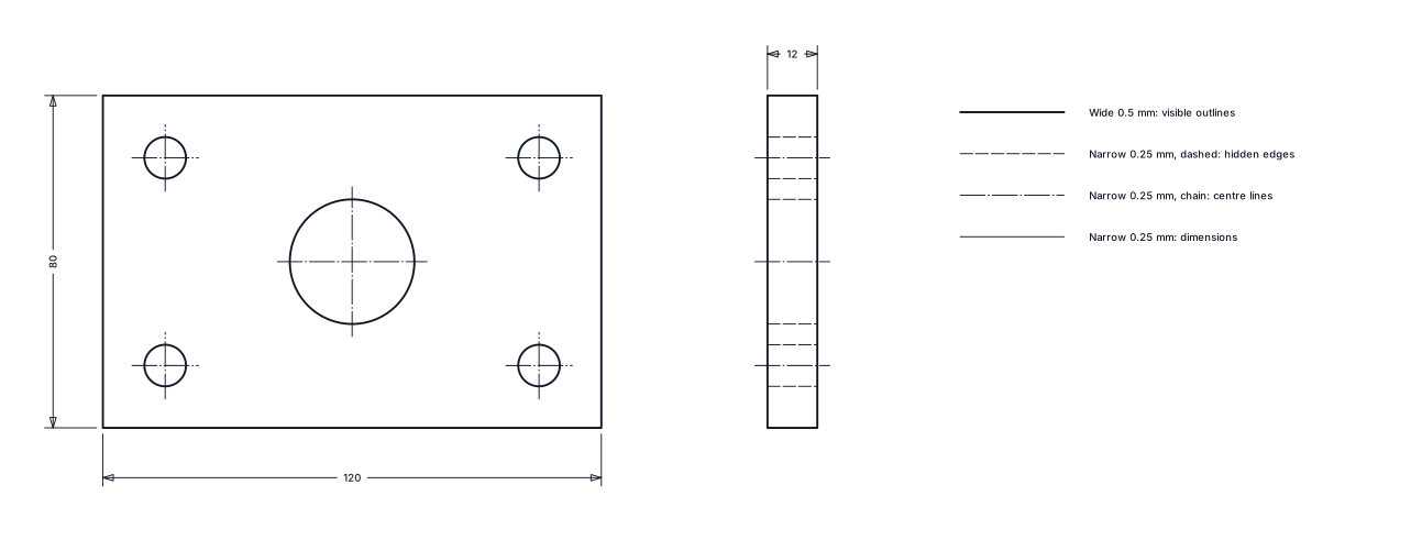
The drawing above shows the 0.5 group in use: the visible outline in the wide 0.5 mm line, and the hidden edges, centre lines and dimensions in the narrow 0.25 mm line, half its width.
When lines fall on top of each other
Two line types often want the same place on the sheet. ISO 128-24 settles it in order:
- A visible outline wins over a hidden one.
- A hidden line wins over a centre line.
- A centre line wins over an extension line.
Draw the one that wins and leave the other out.
Centre lines
A centre line runs a little past the outline it belongs to, and it starts and ends on a dash, not a dot or a gap. Short centre lines, on small holes for instance, are drawn as continuous narrow lines, because a dash pattern can't fit.
Dash and gap lengths come from the pen
The pattern of a broken line isn't a free choice either. ISO 128-2 sizes it as multiples of the line width, d: a dash is 12d, a long dash 24d and a gap 3d. A dashed line therefore reads four to one, dash to gap, whatever pen it's drawn with.
| Line | Pattern, in multiples of the pen width |
|---|---|
| Dashed (hidden) | 12, 3 |
| Centre (long-dashed dotted) | 24, 3, 1, 3 |
| Phantom (long-dashed double-dotted) | 24, 3, 1, 3, 1, 3 |
| Dotted | 1, 3 |
So a hidden line in a 0.25 mm pen has 3 mm dashes and 0.75 mm gaps on the printed sheet. A wide 0.5 mm cutting plane gets long dashes of 12 mm. Because the pattern scales with the pen, a wide broken line and a narrow broken line look like the same line type at two weights, which is the intent.
The catch in CAD is that this length is on the paper, not in the model. If the line type scale is set for the wrong drawing scale, the dashes come out too small to see and the line prints solid. Dashed lines printing solid walks through that fix.
Pen thickness in CAD: tie it to the layer
Whatever program you use, the reliable way to keep line thickness right is to set the width once, on the layer, and never on individual objects. An outline layer gets the wide pen, the hidden, centre, dimension and hatch layers get the narrow one, and a cutting plane layer gets the wide pen with the long-dashed dotted type. If your office names layers to a scheme, the pen belongs in that scheme too; AIA layer standards shows one way to build the names.
In isogram a layer carries a pen from the ISO series, and every line prints at its width on the sheet whatever the scale. You draw at full size in Draft, place the view on a sheet at 1:1, 1:50 or 1:100, and the outline still prints at 0.5 mm. Dimensions, lettering and line types follow ISO or ASME, whichever your office works to. Text works the same way: you set the height on the printed sheet in millimetres and the app works out the rest, as explained in text height for scale.
A quick line weight chart to keep
- Series: 0.13, 0.18, 0.25, 0.35, 0.5, 0.7, 1, 1.4, 2 mm, each √2 times the last.
- Pair: wide at least twice narrow, two steps apart in the series.
- Wide: visible outlines, cutting planes.
- Narrow: dimensions, extension lines, leaders, hatching, hidden lines, centre lines, adjacent parts, breaks.
- Dashes: 12d dash, 3d gap; long dash 24d.
- Priority: visible, then hidden, then centre, then extension.
- Reduction: one paper size down moves every line one step down the series.
If you'd like line widths that hold at every scale without a lookup table, isogram's public beta opens in December 2026 on the Mac and Windows, with Linux following in an update. It's free to test, and you can join the list to get the download link.
Questions
What line thickness is used for visible lines in technical drawing?
Visible outlines and edges are continuous wide lines. In the usual line groups that means 0.5 mm or 0.7 mm, with the narrow lines at 0.25 mm or 0.35 mm.
How thick should hidden lines be in an engineering drawing?
Hidden lines are dashed narrow lines, type 02.1 in ISO 128-2. They take the same narrow width as dimensions and centre lines, so 0.25 mm beside a 0.5 mm outline.
Is a cutting plane line wide or narrow?
A cutting plane is a long-dashed dotted wide line, type 04.2. It's one of the few wide lines on a drawing, alongside visible outlines.
How long should the dashes be on a hidden line?
ISO 128-2 sets the dash at 12 times the line width and the gap at 3 times. With a 0.25 mm pen that's a 3 mm dash and a 0.75 mm gap on the printed sheet.
Can I use three line widths on one drawing?
ISO 128-2 asks for two widths per drawing, a wide and a narrow, with the wide at least twice the narrow. Keeping to one pair makes the outline stand out clearly from the information about it.
10 November 2026
The public beta opens in December.
Join the list and we'll email you the download link when it opens. It's free to test.
Join the listMore guides
- Hatching in engineering drawing: every rule for a section, and whyHatching in engineering drawing per ISO 128-50: the 45° angle, 2.5 to 4 mm spacing, adjacent parts, thin sections, large areas and text, each with why.
- Tolerance block on drawings: both styles, with a worked example of eachHow a tolerance block on drawings states the general tolerance: an ISO 2768 class or a decimal-places block, with worked examples and when each is used.
- Drawing revision letters not used: which ones, why, and what comes after ZWhich revision letters drawings skip and why, the full sequence from A to AA and beyond, and how to write a revision row above the title block.
- Dashed line not showing in AutoCAD layout: the fix, and why it happensDashed line not showing in an AutoCAD layout? Set LTSCALE, PSLTSCALE and MSLTSCALE, run REGENALL, and see why dashes vanish at a viewport scale.
- ISO 5457 A3 border size: the frame, margins, marks and grid, size by sizeThe ISO 5457 A3 border: 20 mm filing margin, 10 mm on the other edges, centring marks, a 50 mm grid and where the title block sits, for A0 to A4.
- Scale 1:50 at A1 printed on A3: why it becomes 1:100An A1 drawing at 1:50 printed on A3 measures 1:100. The A-size arithmetic, a quick converter table, and why to write 1:50 @ A1 with a scale bar.