Tolerance block on drawings: both styles, with a worked example of each
A tolerance block on drawings states the general tolerance: the limits that apply to every dimension with no tolerance of its own. There are two ways to write it. Metric ISO drawings name an ISO 2768 class in the title block (for example ISO 2768-m). Inch and ASME drawings often use a decimal-places block instead, where the number of places on a dimension picks its tolerance (X.X ±0.1, X.XX ±0.01).
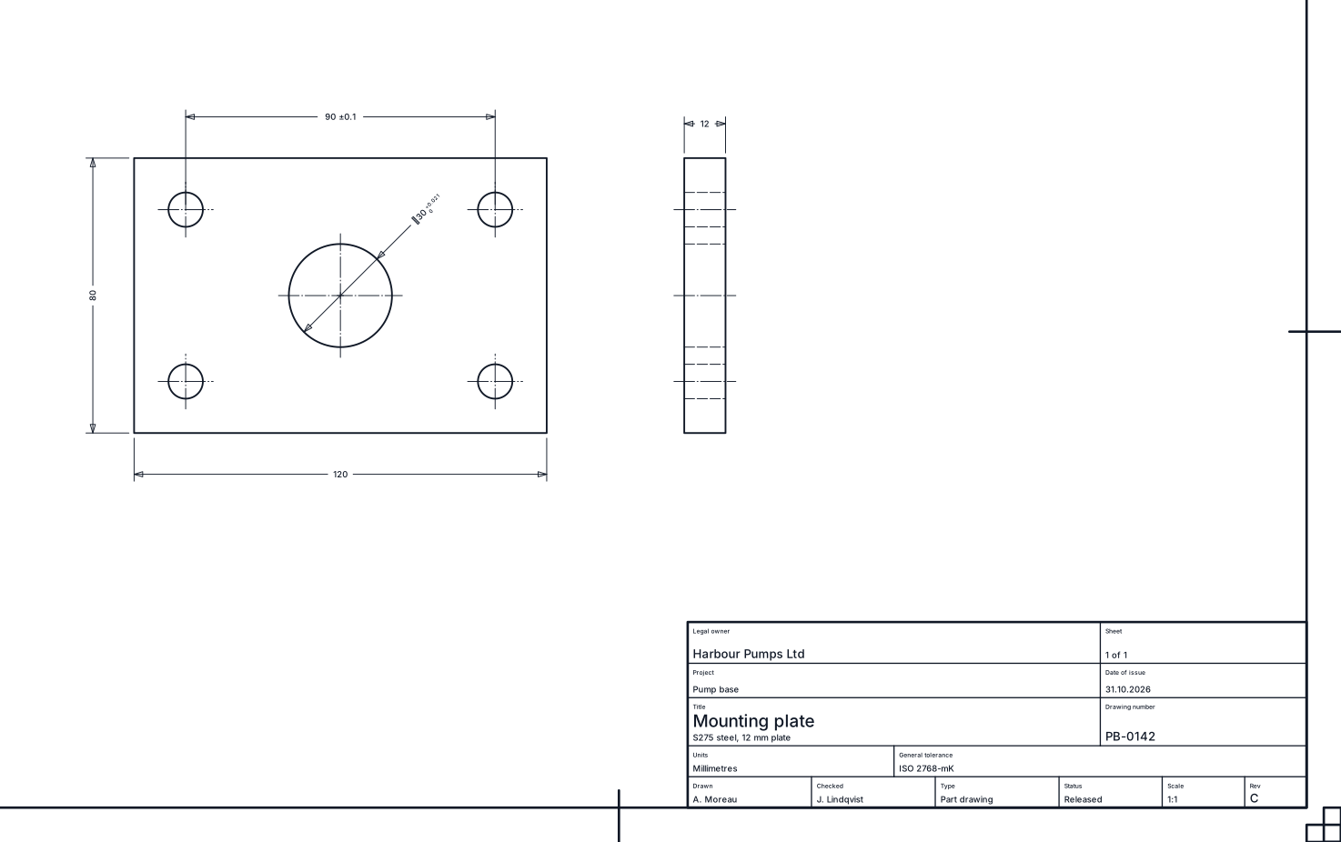
Both styles do the same job. They save you writing a tolerance on every figure, and they tell the machinist or inspector what "no tolerance shown" actually means. Below is a worked example of each, how to read them, and when to use which.
What the general tolerance covers
Under ISO 2768-1, a dimension with no tolerance written on it is held to the general tolerance class the title block names. That's the whole rule. The block doesn't replace tolerances on the dimensions that matter. It covers the rest: overall sizes, chamfers, the outline of a bracket, the length of a slot that only needs to clear something.
Some dimensions sit outside it altogether:
- A dimension with its own tolerance. What's written on the figure wins.
- A theoretically exact dimension. It's boxed, and its tolerance comes from the geometric tolerance that refers to it.
- An auxiliary dimension. It's bracketed and carries no tolerance. It's there for information, not for inspection.
Form, orientation and location aren't toleranced by the general linear block either, and never with a note. ISO 1101 puts them in a frame with the geometric symbols, with datums lettered in a box on a triangle.
Style 1: an ISO 2768 class in the title block
On a metric ISO drawing, the general tolerance is one entry in the title block. ISO 2768-1 gives four classes:
- f: fine
- m: medium
- c: coarse
- v: very coarse
You write the standard and the class, such as ISO 2768-m, and the standard's tables do the rest. The tolerance grows with the size of the feature, so you don't pick a number yourself. You pick a class that suits the process and the part.
Worked example: reading ISO 2768-m
These are the linear tolerances for class m, in millimetres:
| Nominal size (mm) | Permitted deviation (mm) |
|---|---|
| over 0.5 to 3 | ±0.1 |
| 3 to 6 | ±0.1 |
| 6 to 30 | ±0.2 |
| 30 to 120 | ±0.3 |
| 120 to 400 | ±0.5 |
| 400 to 1000 | ±0.8 |
| 1000 to 2000 | ±1.2 |
| 2000 to 4000 | ±2 |
To read an untoleranced dimension, find the band its nominal size falls in and take the deviation. A length in the 6 to 30 band may be off by ±0.2. A length in the 30 to 120 band may be off by ±0.3. A length in the 120 to 400 band may be off by ±0.5. The figure on the drawing stays clean; the inspector looks up the band.
This is the style in the drawing above. Its title block names ISO 2768-mK. The overall sizes carry no tolerance of their own, so they're held to class m. The bore needs to be tighter than that, so it carries its own tolerance, +0.021 and 0, stacked because the two halves differ. The hole centres carry ±0.1, written once because the halves are equal.
Where it goes in the title block
ISO 7200 puts the identification and title at the bottom right of the block, reading the way the sheet reads. The scale, the projection symbol, the unit and the general tolerance class go on the block too, so a reader finds them in one place. The block is at most 180 mm wide and sits against the frame at the bottom right. For the full list of mandatory and optional fields, see the ISO 7200 title block guide.
Style 2: a decimal-places block
The decimal-places style is common on inch and ASME drawings. Instead of naming a standard, the block lists a tolerance for each number of decimal places. The way you write a dimension then selects its tolerance.
Worked example: a decimal-places block
A typical block reads like this:
| Dimension written as | Tolerance |
|---|---|
| X.X | ±0.1 |
| X.XX | ±0.01 |
A dimension written to one place, X.X, holds ±0.1. Write the same size to two places, X.XX, and it holds ±0.01. The figure is the same size; the extra digit is the instruction. So on this kind of drawing, trailing zeros aren't decoration. Dropping one loosens the part, and adding one tightens it.
The important point: the values in a decimal-places block are the company's own, not a standard's. Two companies can both use X.X and X.XX and mean different things. Always read the block on the sheet in front of you, and never assume it matches the last drawing you worked from.
Which style to use
| ISO 2768 class | Decimal-places block | |
|---|---|---|
| Usual setting | Metric ISO drawings | Inch and ASME drawings |
| Where the values come from | The standard's tables | The company's own block |
| What selects the tolerance | The size of the feature | The places written on the figure |
| What you write | The class, such as ISO 2768-m | A small table in the title block |
Use ISO 2768 when you draw to ISO, in millimetres, and want a tolerance that scales with size without thinking about it. A supplier anywhere can look up the class. Use a decimal-places block when you draw in inches to ASME, or when your company already has one and its suppliers know it. Whichever you pick, state it once, in the title block, and don't mix the two on one sheet.
Writing a tolerance on the figure
Whatever the general block says, some dimensions need their own. ISO 129-1 sets out how:
- Deviations go after the figure, upper above lower, both with their sign, in the same unit as the figure. Where the halves differ, they're stacked, like the bore's +0.021 over 0 in the drawing above.
- Equal deviations are written once with ±, like the hole centres' ±0.1.
- Limits give the two sizes instead, larger above.
A common mistake is writing a geometric requirement as a note ("holes to be square to face"). That belongs in a feature control frame, not in text.
Building drawings are different
If you draw buildings rather than parts, you won't find a tolerance block in the title block at all. ISO 2768-1 is clear that building work isn't toleranced on the drawing; the permitted deviations sit in the specification. A building title block carries other things instead, such as a sheet number by discipline and series and a status like for approval or for construction.
How isogram handles it
In isogram, the title block carries the drawing's general tolerance, and a dimension that needs its own writes it on the figure, stacked where the halves differ. Dimensions follow ISO 129-1 or ASME, whichever your office works to, and geometric tolerances and datums are drawn to ASME Y14.5 in proper frames. Auto Dim proposes the dimensions for a whole view of a part; you review them and keep what you want, then add tolerances to the ones that matter.
Before a set is issued, isogram reads every sheet for what a senior drafter would catch, including an empty title block field. A missing tolerance class is exactly the kind of gap that gets a drawing sent back. If you want to try it on your own parts, the public beta opens in December 2026 on Mac and Windows, with Linux following in an update, and it's free to test: join the list.
Questions
Does a bracketed dimension take the general tolerance?
No. A bracketed dimension is an auxiliary dimension under ISO 129-1. It carries no tolerance and is there for information only.
What is the general tolerance for very large parts under ISO 2768-m?
For nominal sizes from 2000 to 4000 mm, ISO 2768-m allows ±2 mm. Between 1000 and 2000 mm it allows ±1.2 mm.
Can I write a flatness or position requirement as a note?
No. Under ISO 1101, form, orientation and location are toleranced with the geometric symbols in a frame, never with a note. Datums are lettered in a box on a triangle.
Do architectural drawings need a general tolerance in the title block?
No. Building work isn't toleranced on the drawing. The permitted deviations are set out in the specification instead.
Are decimal-places tolerance values standard across companies?
No. The values in a decimal-places block are each company's own, not a standard's. Always read the block on the drawing you're working from.
8 November 2026
The public beta opens in December.
Join the list and we'll email you the download link when it opens. It's free to test.
Join the listMore guides
- Drawing revision letters not used: which ones, why, and what comes after ZWhich revision letters drawings skip and why, the full sequence from A to AA and beyond, and how to write a revision row above the title block.
- ISO 5457 A3 border size: the frame, margins, marks and grid, size by sizeThe ISO 5457 A3 border: 20 mm filing margin, 10 mm on the other edges, centring marks, a 50 mm grid and where the title block sits, for A0 to A4.
- Scale 1:50 at A1 printed on A3: why it becomes 1:100An A1 drawing at 1:50 printed on A3 measures 1:100. The A-size arithmetic, a quick converter table, and why to write 1:50 @ A1 with a scale bar.
- ISO 7200 title block, field by field, on any sheet sizeThe ISO 7200 title block field by field: the nine mandatory fields, the optional ones, the 180 mm width limit and where it sits on A0 to A4 sheets.
- AIA layer standards: how a name is built, the layers you need, and N, E, DHow an AIA (NCS) layer name is built from discipline, major group, minor group and status, the layers an architectural set needs, and -N, -E, -D.
- Dashed line not showing in AutoCAD layout: the fix, and why it happensDashed line not showing in an AutoCAD layout? Set LTSCALE, PSLTSCALE and MSLTSCALE, run REGENALL, and see why dashes vanish at a viewport scale.