Text height for scale 1:100: the sum, the chart, and how to stop doing it
The text height for scale 1:100 is the height you want on paper times 100. So 2.5 mm lettering on the printed sheet is 250 mm tall in the drawing, and 3.5 mm is 350 mm. At 1:50 you multiply by 50 instead: 2.5 mm is 125 mm, and 3.5 mm is 175 mm.
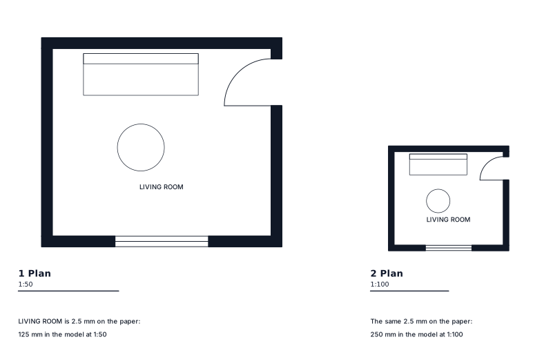
That is the whole rule. Some of the charts you'll find online divide where they should multiply and give you 0.025 for 1:100. That number is for text drawn the wrong way round. If you draw at full size, which you should, the text in the drawing has to be big, because the plot shrinks everything a hundred times.
The rule, stated once
Model-space text height is the paper height times the scale denominator. The denominator is the second number in the scale: the 100 in 1:100, the 50 in 1:50. That number is also what AutoCAD users call the text height scale factor.
- 2.5 mm at 1:100 is 2.5 × 100 = 250 mm in the drawing.
- 3.5 mm at 1:50 is 3.5 × 50 = 175 mm in the drawing.
- 5 mm at 1:20 is 5 × 20 = 100 mm in the drawing.
These figures assume you draw in millimetres. If your drawing unit is the metre, move the decimal point three places: 250 mm becomes 0.25. That is probably where the 0.025 figures come from, someone mixing up units with scale. Check your units before you trust any chart, this one included.
For an enlargement the sum goes the other way, because the drawing is smaller than the print. At 2:1, 2.5 mm on paper is 1.25 mm in the drawing.
Text height scale chart
Paper heights across the top, scale down the side. Every figure in the body of the table is the height to type into a full-size drawing in millimetres.
| Scale | 1.8 mm | 2.5 mm | 3.5 mm | 5 mm | 7 mm |
|---|---|---|---|---|---|
| 1:1 | 1.8 | 2.5 | 3.5 | 5 | 7 |
| 1:5 | 9 | 12.5 | 17.5 | 25 | 35 |
| 1:10 | 18 | 25 | 35 | 50 | 70 |
| 1:20 | 36 | 50 | 70 | 100 | 140 |
| 1:50 | 90 | 125 | 175 | 250 | 350 |
| 1:100 | 180 | 250 | 350 | 500 | 700 |
| 1:200 | 360 | 500 | 700 | 1000 | 1400 |
| 1:500 | 900 | 1250 | 1750 | 2500 | 3500 |
The scales in the left column are all from the permitted list in ISO 5455. A scale there is full size, a reduction of 1:2, 1:5, 1:10 and their decimal multiples, or an enlargement of 2:1, 5:1, 10:1 and theirs. Nothing in between, so you'll never need a row for 1:75.
Which paper height to pick
The chart only helps once you know the paper height. ISO 3098-1 gives a series: 1.8, 2.5, 3.5, 5, 7, 10, 14 and 20 mm. Each step is √2 larger than the last, the same ratio as one A size to the next. A drawing made for A1 and reduced to A3 drops each line of text neatly to a smaller standard size, and it still reads.
The usual choices:
- Dimension figures: 2.5 mm.
- Notes: 3.5 mm.
- Titles: 5 or 7 mm.
The common convention ties this to the sheet: dimension figures and notes at 2.5 mm on A4 to A2, and at 3.5 mm on A1 and A0, with titles a size or two larger. Don't go under 1.8 mm. Nothing smaller is legible on a plot.
The proportions behind the height
The height is the capital height, h. For lettering B, the one CAD uses, the rest follows from it:
- Stroke width is h/10, so 0.25 mm for 2.5 mm text. (Lettering A uses h/14.)
- Lower-case letters are 0.7h.
- The gap between characters is 0.2h.
- Lines of text sit at least 1.4h apart, so 3.5 mm between lines of 2.5 mm text.
Upright is the default. Sloped lettering leans 15° from vertical. Whichever you use, ISO 129-1 asks that text reads from the bottom or the right-hand edge of the sheet, never upside down, and that no line crosses it.
Which scale for which drawing
The usual convention for building work: site plans at 1:500 to 1:1250, floor plans and elevations at 1:100 or 1:50, sections at 1:50 or 1:20, details at 1:10 to 1:1. Mechanical parts go at 1:1 or 1:2, and small parts at 2:1 or 5:1. Choose the scale so the detail reads, not so the text fits.
Whatever the scale, the dimension figure is always the true size. A wall 3600 mm long is dimensioned 3600 at 1:100 and at 1:50. And the drawing is never scaled off with a rule. The scale is written in the title block as SCALE 1:50; where a sheet holds views at more than one scale, the main one goes in the title block and every other view is titled with its own.
Where the sum goes wrong
Multiplying 2.5 by 100 isn't hard. The trouble is what happens after.
- Mixed scales on one sheet. A 1:50 plan with a 1:10 detail beside it needs two text heights for the same printed size: 125 mm and 25 mm. Put the wrong one in the detail and it prints at 12.5 mm.
- A change of scale late on. The client wants the plan at 1:50 instead of 1:100. Every note, every dimension style, every title now has to halve.
- Units. A drawing in metres and a chart in millimetres give you text a thousand times wrong, and you don't find out until the plot.
- Blocks and title blocks that were drawn for one scale and inserted at another.
AutoCAD's own answer is annotative text. You set the text at its paper height and give it an annotation scale, and the text sizes itself to the viewport's scale. Autodesk documents it as the way to handle exactly this problem, and it works well once a template is set up for it. Many offices still use the older way of typing the multiplied height into each text style, which is why the charts exist.
Setting lettering in paper millimetres instead
The cleaner fix is to stop treating text height as a size in the drawing at all. It is a size on paper. That is how ISO 3098 defines it, and that is what you actually care about.
This is how isogram handles it. You set text height as the height on the printed sheet, in millimetres, and the app works out its size on the drawing from the scale. Pick 2.5 mm and it prints at 2.5 mm, whether the view is 1:100, 1:50 or 1:5. There's no factor to multiply, so there's nothing to get wrong, and a scale change late in the job doesn't mean editing every note.
The rest follows the same standards: lettering to ISO 3098, dimensions to ISO 129-1, scales to ISO 5455 and sheets to ISO 5457 (or ASME, if your office works to that). You draw at full size in Draft, lay out the sheets with viewports, title blocks and revisions in Sheets, and publish the set as one PDF. Before the set goes out, isogram reads every sheet for what a senior drafter would catch, including lettering too small to print.
If you're coming from AutoCAD, the habits carry over. The command line takes the familiar aliases, F3, F8 and F10 do what you expect, and the AutoCAD commands guide lists the rest. Your existing DWG files open, from R13 to the 2018 format; the guide to opening DWG files covers what comes across, and dimensions keep the figure AutoCAD wrote.
The short version
- Text height in the drawing = paper height × scale denominator.
- At 1:100: 2.5 mm is 250 mm, 3.5 mm is 350 mm, 5 mm is 500 mm.
- At 1:50: 2.5 mm is 125 mm, 3.5 mm is 175 mm, 5 mm is 250 mm.
- Pick paper heights from 1.8, 2.5, 3.5, 5, 7, 10, 14, 20 mm, and never go below 1.8 mm.
- Or set heights in paper millimetres and let the software do the sum.
isogram's public beta opens in December 2026 on the Mac and Windows, with Linux following in an update, and it's free to test. Join the list and you'll be emailed the download link.
Questions
What is the text height scale factor for 1:100 in AutoCAD?
The factor is 100, the scale denominator. Multiply the height you want on paper by 100, so 2.5 mm text is 250 mm in a full-size drawing in millimetres.
What size text should I use for dimensions?
Dimension figures are usually 2.5 mm on the printed sheet, and 3.5 mm on A1 and A0 sheets. Notes are usually 3.5 mm and titles 5 or 7 mm.
What is the smallest text height that will print legibly?
1.8 mm on paper, the smallest size in the ISO 3098 series. Anything under that won't read on a plot.
Why are standard text heights 1.8, 2.5, 3.5, 5 and 7 mm?
Each step is √2 larger than the one before, the same ratio as one A sheet to the next. When a drawing is reduced by one sheet size, each height lands on the next standard size down.
Do I divide or multiply the text height by the scale?
Multiply, when you draw at full size. Dividing gives text a hundred times too small at 1:100, unless your drawing units are different from your paper units.
31 October 2026
The public beta opens in December.
Join the list and we'll email you the download link when it opens. It's free to test.
Join the listMore guides
- Scale 1:50 at A1 printed on A3: why it becomes 1:100An A1 drawing at 1:50 printed on A3 measures 1:100. The A-size arithmetic, a quick converter table, and why to write 1:50 @ A1 with a scale bar.
- Dashed line not showing in AutoCAD layout: the fix, and why it happensDashed line not showing in an AutoCAD layout? Set LTSCALE, PSLTSCALE and MSLTSCALE, run REGENALL, and see why dashes vanish at a viewport scale.
- AIA layer standards: how a name is built, the layers you need, and N, E, DHow an AIA (NCS) layer name is built from discipline, major group, minor group and status, the layers an architectural set needs, and -N, -E, -D.
- Drawing revision letters not used: which ones, why, and what comes after ZWhich revision letters drawings skip and why, the full sequence from A to AA and beyond, and how to write a revision row above the title block.
- ISO 5457 A3 border size: the frame, margins, marks and grid, size by sizeThe ISO 5457 A3 border: 20 mm filing margin, 10 mm on the other edges, centring marks, a 50 mm grid and where the title block sits, for A0 to A4.
- ISO 7200 title block, field by field, on any sheet sizeThe ISO 7200 title block field by field: the nine mandatory fields, the optional ones, the 180 mm width limit and where it sits on A0 to A4 sheets.
AutoCAD is a registered trademark of Autodesk, Inc. isogram is not affiliated with or endorsed by Autodesk.