Chain vs baseline dimensioning: the same part both ways, and how the tolerance adds up
In chain vs baseline dimensioning, a chain locates each feature from the one before it, so every link's tolerance adds onto the next. A baseline (parallel dimensioning) locates every feature from one datum edge, so each feature carries only its own tolerance. Use a baseline when position on the part matters and a chain when the distance between neighbours matters. Never close a chain.
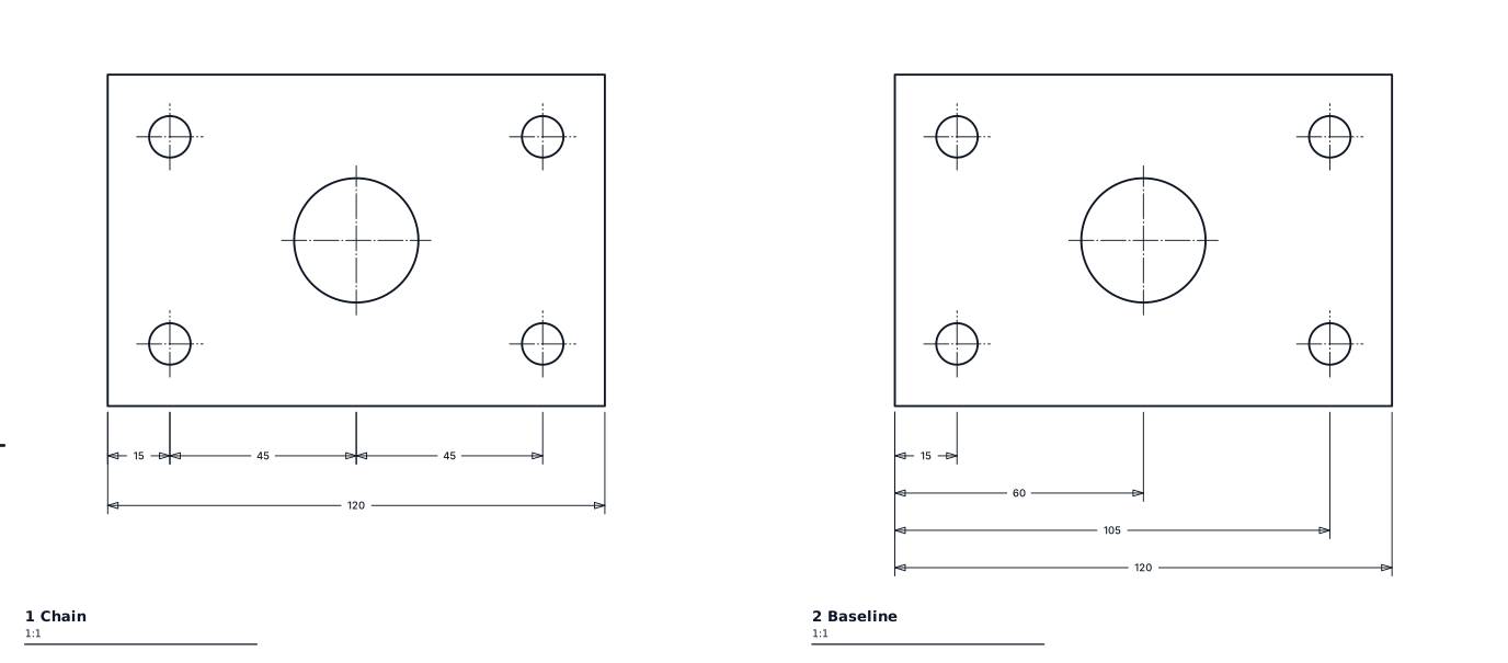
The drawing above shows one plate both ways at 1:1. The rest of this page walks through what each arrangement means for the part that comes off the machine.
The three arrangements
ISO 129-1 names three ways to lay out a row of linear dimensions:
- Chain dimensioning. Dimensions run end to end along one line. Each starts where the last one stopped.
- Parallel (baseline) dimensioning. Every dimension starts at the same datum edge. They stack as parallel rows, spaced evenly, with the shortest nearest the outline.
- Running (superimposed) dimensioning. This is parallel dimensioning folded onto one line. There is one origin and each figure gives the distance from it. It saves space. It is what most people mean by ordinate dimensioning.
Each single dimension is the same thing whichever way it is arranged. It has a dimension line parallel to the length it gives, an extension line at each end, a terminator at each end and one value, all in continuous narrow line. The arrangement only changes where each dimension starts. That choice decides how errors build up.
The plate, side by side
The plate is 120 long and has three hole and bore centres along it. Here are the same three centres in both arrangements:
| Feature | Chain: dimension given | Baseline: dimension given | Position from left edge |
|---|---|---|---|
| First centre | 15 (from left edge) | 15 | 15 |
| Second centre | 45 (from first centre) | 60 | 60 |
| Third centre | 45 (from second centre) | 105 | 105 |
| Right edge | left open; overall 120 given | 120 | 120 |
Both columns describe the same nominal part. A machinist who hits every figure exactly makes the same plate from either one. The two drawings only differ once you allow each figure its tolerance, and a real part always needs that allowance.
How the tolerance adds up along a chain
Give every dimension the same tolerance, ±t. On the chain, look at where the third centre can end up.
- The first centre is 15 from the edge, so it can be off by ±t.
- The second centre is 45 from the first. The first centre may already be off by ±t, and this link adds its own ±t. The second centre can be off by ±2t from the edge.
- The third centre is 45 from the second. Add another ±t. The third centre can be off by ±3t from the edge.
That is the general rule. Along a chain of n dimensions, each toleranced ±t, the worst case for the end feature, measured from the start, is ±n·t. Three links give three times the tolerance written on any one of them. Nothing on the drawing warns the reader of this. They have to do the sum themselves.
On the baseline drawing, the third centre is dimensioned 105 straight from the edge. Its worst case from that edge is ±t, the tolerance on that one figure. The error from the first centre has no route to the third, because the third was never measured from it.
The catch with a baseline
A baseline does not remove stack-up. It moves it. Ask instead how far apart the first and second centres can be. On the chain, that distance is the 45, given directly, so it holds to ±t. On the baseline, it comes from 60 minus 15. Each of those carries ±t, so the gap between the two centres can vary by ±2t.
So the rule is not "baseline good, chain bad". Each arrangement holds tightest the distance it states directly. The question is which distance matters to the part.
Choose by what the part has to do
A size that matters to how the part works or mates should be stated directly. Give it as one figure, measured from the feature it is located from. It should never be the sum of other dimensions, because then it collects all their tolerances. ISO 129-1 sets this as a general principle, and ASME Y14.5 says the same.
- Features that locate the part in an assembly should come from the datum edges the part sits against. Use parallel dimensions, with the shortest nearest the outline. The designer decides which edges are the datums. The bottom and left edge are what a reader expects if nothing else is said.
- Features that work as a group should be located from each other or from the feature they serve. Two holes that take one bracket, or dowels round a bore, are examples. Here a short chain, or dimensions from the bore, states the size that matters directly.
- A feature symmetric about a centre line is dimensioned across the line. A feature standing on the centre line needs no location along that axis. Draw the centre line to say so.
- Equally spaced features are given as the count of spaces times the pitch, with the total in brackets or after an equals sign. The first one is located from its datum. On a circle, give the pitch circle diameter and n × ⌀ EQS.
Most real drawings mix these. A part might be located from its datum edges by a baseline, with a short chain inside one group of holes, because that gap is the one that has to fit.
Why a chain is never closed
On the plate, the chain gives 15, 45, 45 and the overall 120. It leaves out the last link, from the third centre to the right edge. Nominally that link is 15. Why not write it?
If you give the overall and every link, the part is dimensioned twice. The four links add to 120, and the overall says 120 as well. With tolerances on all of them, the two can contradict each other. Suppose every link comes in at its upper limit. The links then add to more than the overall allows. No part can satisfy both, and nobody can tell which figure wins.
ISO 129-1 settles it: a chain of dimensions is never closed. Leave one link off. That link is the one whose size matters least, because it takes up all the accumulated error. If the reader needs it for convenience, write it in brackets, like (15). Brackets mark an auxiliary dimension. It is for information only, and it is not toleranced or inspected.
The same thinking runs through the rule that each feature is dimensioned once. Use the view that shows it clearest, and never dimension from a hidden line. Give no more dimensions than the part needs to be made and checked. A closed chain breaks that rule by giving one length twice.
Laying them out on the sheet
A few conventions keep either arrangement readable:
- The first dimension line stands about 8 to 10 mm off the outline. Each further row stands about 6 to 8 mm beyond it. For parallel rows, keep the spacing even and put the shortest dimension nearest the part.
- Extension lines are drawn at right angles to the length measured. They run about 2 mm past the dimension line and may leave a small gap from the outline.
- Pick one terminator and use it throughout the drawing: a closed filled arrowhead, an open arrowhead, a 45° oblique stroke or a dot. An arrowhead is about three times as long as it is wide.
- The value sits above the dimension line, near its middle and clear of it. It reads from the bottom or from the right of the sheet, and no line crosses it.
- State the unit once, in the title block, and leave it off every linear figure. Mechanical work uses 1 or 2 decimals in mm, with trailing zeros dropped. Figures are at least 2.5 mm high on paper, and 3.5 mm on A1 and A0. The sum for text height at a given scale is in text height for scale.
Where the tolerance on each figure comes from matters too. If most dimensions take a general tolerance from the title block, the stack-up sum uses that value as t. Tolerance block on drawings covers both styles of that block.
Doing it in isogram
isogram draws dimensions to ISO 129-1 or to ASME, whichever your office works to. Geometric tolerances and datums are drawn to ASME Y14.5. Text height is set as the height on the printed sheet, in millimetres, and the app works out its size on the drawing from the scale. Auto Dim proposes the dimensions for a whole view of a part. You review them and keep the ones you want. Deciding which edges are datums, and which link of a chain stays open, remains your call.
Before a set is issued, isogram reads every sheet for what a senior drafter would catch. That includes lettering too small to print. It comes to the Mac and Windows first, with Linux following in an update. It is free to test, and you can sign up for early release to get the download link.
Questions
Is parallel dimensioning the same as baseline dimensioning?
Yes. ISO 129-1 calls it parallel dimensioning, and CAD programs usually call it baseline. Every dimension starts from the same datum, and the rows are spaced evenly with the shortest nearest the outline.
What is the difference between ordinate dimensioning and linear dimensioning?
Ordinate dimensioning is what ISO 129-1 calls running (superimposed) dimensioning: every figure is a distance from one origin, set along a single line. Each one is still a linear dimension. Because all are measured from the same origin, tolerances behave as they do with a baseline, not a chain.
Can I give the overall length and every dimension in a chain?
Not as toleranced dimensions. A chain is never closed, so leave one link off. If the reader needs it, write it in brackets as an auxiliary dimension, which is for information only.
How much tolerance builds up along a chain of dimensions?
In the worst case, a chain of n dimensions each toleranced ±t lets the last feature vary by ±n·t from the start. The same feature dimensioned directly from a baseline varies by only ±t.
Which edge should be the datum for baseline dimensions?
The edges the part is located against in use, which is the designer's decision. If nothing says otherwise, readers expect the bottom and left edges.
17 November 2026
Sign up for early release.
We'll email you the download link. It's free to test.
Sign upMore guides
- Tolerance block on drawings: both styles, with a worked example of eachHow a tolerance block on drawings states the general tolerance: an ISO 2768 class or a decimal-places block, with worked examples and when each is used.
- ISO 7200 title block, field by field, on any sheet sizeThe ISO 7200 title block field by field: the nine mandatory fields, the optional ones, the 180 mm width limit and where it sits on A0 to A4 sheets.
- ISO 2768-mK meaning: what the m and the K say, with the medium tolerance tableWhat ISO 2768-mK means on a drawing: m is the medium class for lengths and angles, K the geometric class. The medium table and how to read a plain size.
- What should a title block include: the required fields, the extras, and where it goesThe fields every title block must have under ISO 7200, the ones engineering and architecture add, and where the block sits on the sheet.
- Line weights for floor plans: cut, below, overhead, and how few pens it takesThe line weight hierarchy for floor plans and site plans: what the cut, the things below and the things overhead are drawn in, with ISO pen widths.
- NCS sheet numbering: reading A-101, the sheet type digits and the set orderHow an NCS sheet number like A-101 is read: discipline, sheet type digit and sequence, what each digit 0 to 9 means, and the order the set is bound in.